
The CNC machining process turns an approved design into a measured part through a sequence of controlled handoffs. Each handoff can introduce a different error: a vague drawing note, a wrong stock grade, a shifted work offset, or an inspection plan that overlooks the mating feature. This process guide follows one custom component from file receipt through repeat production. Buyers can use it to ask better questions and define which evidence they expect before a shipment leaves the shop.
1. Which files define a CNC machining job?
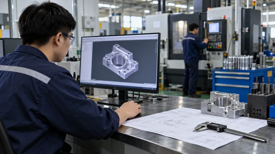
A machinist needs more than a picture of the part. The 3D model carries geometry, while the 2D drawing usually states dimensions, tolerances, datums, finish, and notes. An RFQ should also name material grade, quantity, delivery location, and any required reports. When a model and drawing disagree, production needs a documented answer before programming starts. The same applies when two files carry different revisions. For functional features, a drawing should show what controls fit and how that feature will be measured. ASME describes GD&T as a shared language for design requirements.
The handoff begins here. Record the exact file set and revision used for quotation. If an NDA is required, settle access before sending drawings; Vastion provides a confidentiality policy as a starting point. A buyer should then ask the supplier to list ambiguities instead of pricing around silent assumptions.
- Supply the model and controlled drawing together.
- Mark critical mating or sealing features.
- State required material and inspection evidence.
Input file control
| Input | Purpose | Check before release |
|---|---|---|
| 3D model | Defines shape | Matches the drawing revision |
| 2D drawing | Defines acceptance | Tolerances and datums are clear |
| RFQ note | Defines order scope | Quantity, finish, and reports are named |
For each new revision, resend the full approved file package rather than an isolated screenshot of the change.
2. How does the shop test manufacturability before programming?
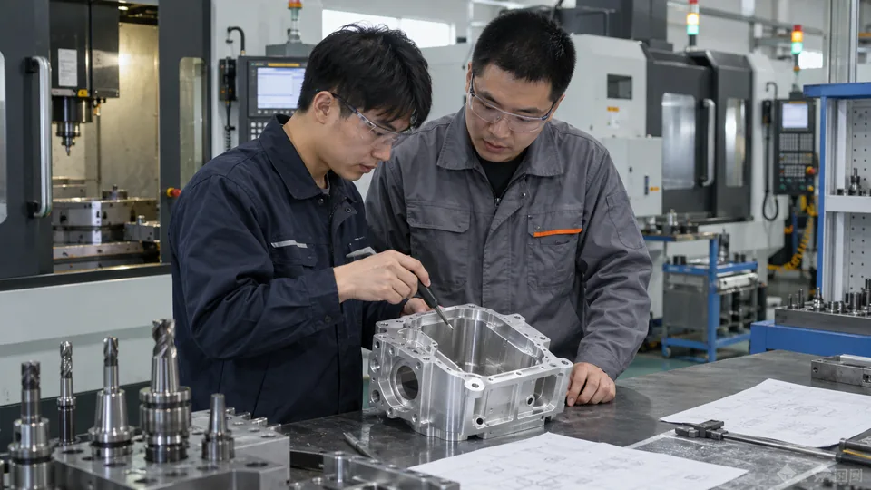
Process planning starts by checking whether every feature can be reached with available tools and held without distortion. An internal corner may need a cutter smaller than the drawing allows. A deep slot can require a long, flexible tool. A thin wall may move after roughing releases stress. The planner also decides which faces can share a setup and whether a turned blank should precede milling. This review is specific to geometry and order volume; a plausible route for one prototype may be slow for hundreds of repeat parts.
Ask for the objection list. A useful DFM response names the feature, its consequence, and a proposed change. The buyer can then accept the change, keep the requirement and pay for a harder route, or use another process. Vastion’s CNC service page gives the broad process context. For some designs, sheet metal fabrication or die casting may deserve a separate quote.
- Identify inaccessible faces and special cutters.
- Count likely reclamping operations.
- Approve any design revision in writing.
DFM decision record
| Finding | Potential effect | Buyer decision |
|---|---|---|
| Sharp internal corner | Small tool or secondary operation | Allow a radius or retain the feature |
| Deep narrow cavity | Tool reach and chip removal | Change access or accept added work |
| Thin wall | Deflection during cutting | Change support or thickness |
Request a revised drawing when the accepted DFM change affects fit, strength, or assembly.
3. How are stock and material prepared?
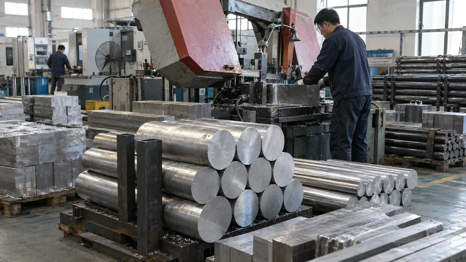
After process approval, the shop obtains stock with the specified grade, condition, and form. A label saying only “aluminum” or “stainless steel” is too broad for controlled production. Purchasing may need a material certificate, a lot identifier, or an approved source. Stock is then cut with enough excess for facing, workholding, and subsequent machining. If the blank comes from casting or forging, its datum surfaces and remaining stock must support the planned route. Material preparation also affects lead time when a grade is hard to obtain.
Traceability starts before cutting. A certificate is useful only if the delivered parts can be related to the stock lot it describes. For a prototype, a simple labeled bag and job traveler may be sufficient. A regulated application may require a stronger chain of records. The buyer should specify the needed level before the shop quotes, rather than ask for it after shipment.
- Specify grade and condition, not a material family alone.
- State whether substitutes are allowed.
- Identify certificate and lot tracking requirements.
Material release check
| Item | Shop check | Buyer evidence |
|---|---|---|
| Grade | Matches purchase specification | Certificate when required |
| Blank size | Supports machining and clamping | Approved process plan |
| Lot identity | Follows parts through production | Traceable label or record |
Ask which material condition the quote assumes if heat treatment or post-process coating remains undecided.
4. How does CAM turn geometry into machine instructions?
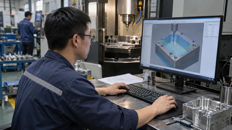
The programmer imports the approved model into CAM software and selects the stock, coordinate system, cutters, and operations. A roughing path removes bulk material while leaving allowance for finishing. Finishing paths target dimensions and surface requirements. Drilling, tapping, and chamfering may follow as separate operations. CAM then posts the plan into machine-specific code. A simulation can reveal collisions or unexpected stock left behind, but it cannot prove the physical fixture and tool offsets are correct. Manufacturing.gov explains CAM as the connection between a digital design and instructions for automated equipment.
Programming is a controlled translation. The program, setup sheet, and drawing revision should agree. A change to the model can invalidate an old tool path. A part with rotational features may need both milling and the CNC turning route; the operations must reference consistent datums.
- Simulate stock removal and tool clearance.
- Record the postprocessor and machine route.
- Regenerate the program after an approved design change.
Programming outputs
| Output | What it controls | Review point |
|---|---|---|
| Tool path | Cutting sequence | Material left for finishing |
| Machine code | Axis and spindle commands | Correct machine and revision |
| Setup sheet | Tools and datum locations | Matches the physical fixture |
Ask the supplier to identify any programmed assumption that the drawing does not make explicit.
5. How is the workpiece located and clamped?
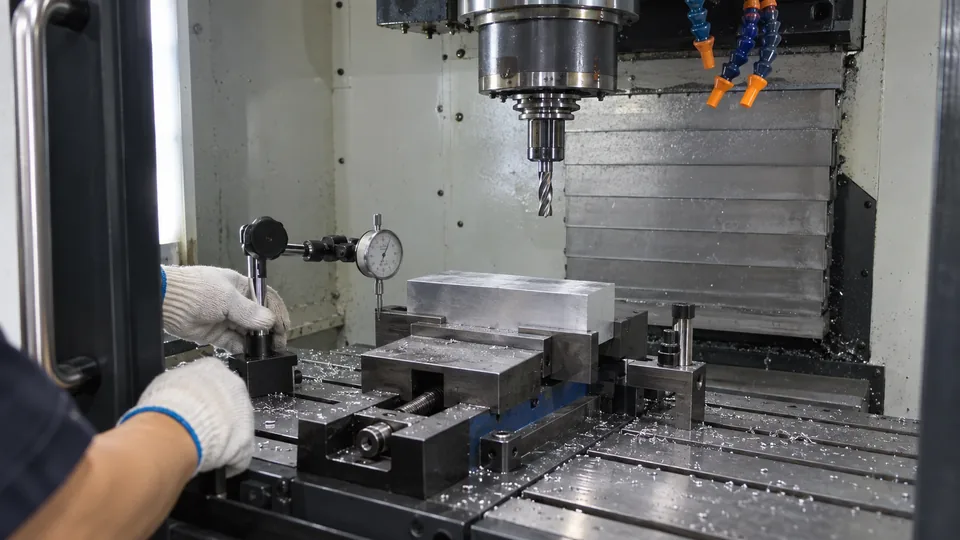
The setup team mounts a vise, fixture, collet, or other workholding device on the machine. It then places the stock against known locating surfaces and establishes a work coordinate system. Clamping must resist cutting forces without bending the part or blocking tool access. The datum plan should link those locating surfaces to drawing requirements. A part machined on multiple sides may need a second fixture or a controlled transfer to another machine. Each transfer adds an opportunity for positional error and requires a check.
The fixture is part of the process. A perfectly simulated path can fail if the real clamp lies in the cutter’s route. Likewise, a thin enclosure can move when tightened too hard. For repeat production, a fixture should allow an operator to load parts consistently and verify seating. The buyer should ask how critical features remain aligned across setups.
- Check part seating and clamping pressure.
- Verify clearance around tools and fixtures.
- Record datum transfer between setups.
Workholding risks
| Condition | Possible result | Control |
|---|---|---|
| Stock not fully seated | Shifted features | Clean locators and seating check |
| Excess clamp force | Temporary distortion | Supported contact points |
| Fixture in tool path | Collision | Dry run and clearance review |
Request a setup review if a drawing relies on close alignment between features cut in different orientations.
6. How are tools and offsets checked before the first cut?
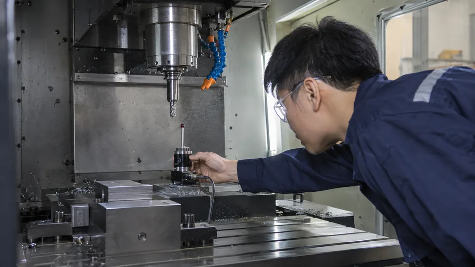
Before cutting, the operator installs the specified tools and measures their length or diameter offsets. The machine also needs a work offset that locates the part in its coordinate system. A wrong sign, missing tool length, or misidentified fixture can cause scrap or a collision. Shops commonly check the setup through a controlled prove-out: review program lines, use a safe path or dry run where appropriate, and watch the first approach to the part. The exact check depends on machine control and process risk.
This is the last cheap correction point. A correction made before cutting costs far less than a scrapped blank. Tool condition also matters. A worn finishing tool can change dimensions and leave a poor surface even when code is unchanged. An operator should know which offsets may be adjusted during production and which changes need engineering approval.
- Confirm tool identity and measured offsets.
- Check work origin against the setup sheet.
- Record any adjustment made during prove-out.
Pre-cut controls
| Control | Question | Record |
|---|---|---|
| Tool list | Are cutters and holders correct? | Setup sheet |
| Work offset | Does origin match the fixture? | Probing or setup result |
| Program revision | Is the approved code loaded? | Job traveler |
Ask for a first-part approval point before the shop releases the full production quantity.
7. What happens during roughing and finishing?
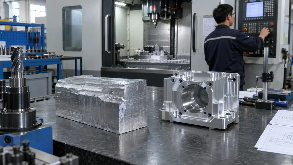
Roughing removes most excess stock. The strategy should leave enough material for a stable finishing pass without overloading the tool or deforming the part. Intermediate operations may create holes, slots, or threads while the piece remains well supported. Finishing then brings critical surfaces closer to their specified dimensions and appearance. Depending on geometry, the shop may deburr between operations so a raised edge cannot prevent proper seating in the next fixture. Chip removal and coolant management influence tool life and surface condition.
Sequence affects the final measurement. A thin wall can change shape after surrounding stock is removed. A threaded hole may need protection during coating. A cosmetic face can be damaged by later clamping. The route should account for these interactions. Buyers need not choose feeds and speeds, but they should identify surfaces whose function or appearance cannot be compromised.
- Leave finishing stock where necessary.
- Protect functional surfaces during later setups.
- Deburr before a part seats against a new datum.
Operation sequence
| Operation | Typical purpose | Watch point |
|---|---|---|
| Roughing | Remove bulk stock | Part stability |
| Intermediate features | Produce holes or threads | Tool access and burrs |
| Finishing | Reach final surfaces | Dimensions and appearance |
Ask which features are finished after all major stock removal if distortion is a concern.
8. How is the first part accepted before the run continues?
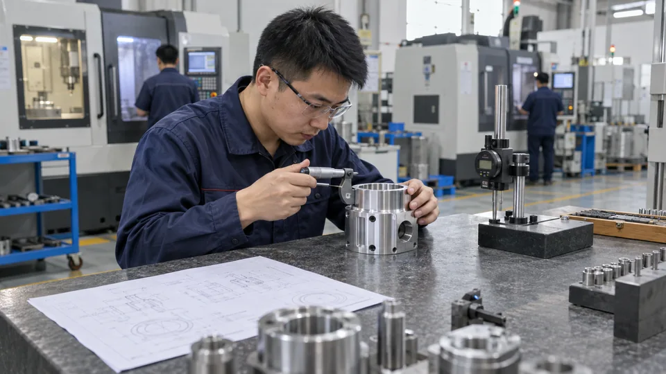
The first completed part should be compared with the approved drawing, not merely placed beside a sample. Inspection may use calipers, micrometers, bore gauges, height gauges, a coordinate measuring machine, or application-specific tests. The method must match the feature and required tolerance. A first-article report can document actual values for critical dimensions, along with the drawing revision and measurement approach. NIST’s on-machine measurement work discusses how measurements fit machining operations; measurement on a machine and independent acceptance are distinct decisions.
Approval should name the evidence. A buyer might accept a measured bore and hole pattern before a small batch proceeds. A different product may require a coating sample or fit test as well. Vastion’s industry page shows varied applications, but an industry label never substitutes for project-specific acceptance criteria.
- Measure features tied to fit and function.
- Confirm revision and material identity.
- Resolve nonconformities before repeat cutting.
First-part decision
| Result | Next action | Required record |
|---|---|---|
| All critical checks pass | Release the run | Approved first-part report |
| Recoverable deviation | Adjust the setup | Correction and recheck |
| Drawing conflict | Pause production | Buyer-approved clarification |
Specify who can authorize a deviation before an urgent delivery creates pressure to accept unclear parts.
9. Where do deburring, finishing, and final inspection fit?
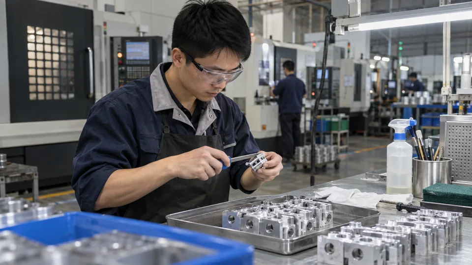
Machining may leave burrs, tool marks, or surfaces that need a separate finish. Deburring removes sharp or loose edges; it must not round a functional edge beyond its drawing limit. Cleaning removes chips and residue before coating, packaging, or assembly. If anodizing, plating, powder coating, or another treatment is specified, the process route should state masking and which dimensions apply after finishing. Vastion’s surface treatment page lists finish options. Suitability, thickness, appearance, and acceptance criteria still need project-level agreement.
Final inspection closes the loop. It checks the finished state against the correct revision and release criteria. A part may pass machining dimensions yet fail after coating changes a tight fit. Packaging should protect measured surfaces during transport. If a report is required, it should identify the relevant lot and inspection result, not merely say “pass.”
- Define deburring limits and protected edges.
- Identify dimensions controlled after finishing.
- Link shipment records to the inspected lot.
Release package
| Item | Why it matters | Buyer check |
|---|---|---|
| Final part | Must meet finished requirements | Visual and dimensional acceptance |
| Inspection report | Shows measured evidence | Correct lot and revision |
| Packaging | Protects critical surfaces | No movement or contact damage |
Require a sample of the final finish when appearance matters as much as dimensional fit.
10. How does a proven setup become a repeatable order?
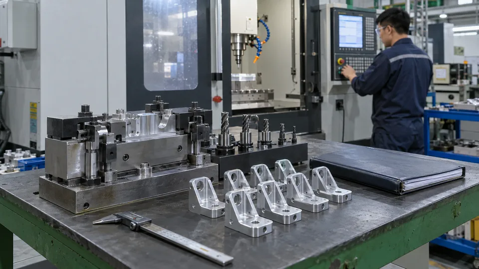
Repeat production depends on preserving more than the CNC program. The shop also needs the approved drawing, setup sheet, tool list, fixture details, work offsets, inspection plan, and change history. A new material lot, replacement cutter, revised drawing, or different machine may require another first-part check. The degree of revalidation should match the change and the part’s risk. Buyers can help by using clear purchase-order revisions and by telling the supplier which records must accompany each lot.
Close every open assumption before reorder. If a prototype passed after an undocumented offset change, a later run may drift. Ask the supplier to retain the approved route and explain what will trigger reapproval. When requesting a new quote, send the current drawing and expected quantity tiers through Vastion’s contact page. The process record gives both sides a shared checklist, while the approved drawing remains the acceptance authority.
- Archive the approved setup and inspection plan.
- Control drawing, program, and material revisions.
- Define the trigger for another first-part approval.
Before the next order, compare its document package with the last accepted lot and resolve every difference in writing.
Frequently asked questions
Q1: Does a CAD model replace the engineering drawing?
No. A model shows geometry, but the drawing or approved digital definition must state acceptance requirements clearly.
Q2: Why is a dry run used before machining?
It can help check program motion and tool clearance before a cutter engages the workpiece. The shop still needs to verify the physical setup.
Q3: What is a first-article inspection?
It is a documented check of an initial part against specified requirements before continuing a new or changed production setup.
Q4: Can the same program run on a different CNC machine?
Not without review. Machine controls, fixtures, offsets, tools, and postprocessing can differ.
Q5: What should accompany a repeat order?
Send the current drawing revision, quantity, material and finish requirements, and any change in inspection or delivery terms.
