
CNC milling machine types differ in spindle orientation, travel, construction and available rotary motion. Buyers can overpay for a machine label while missing the actual constraint: can the shop hold, reach and inspect their part? This guide compares machine layouts and axis options using part geometry, setup count and production needs rather than a simple “more axes is better” ranking.
1. What are the main CNC milling machine types?
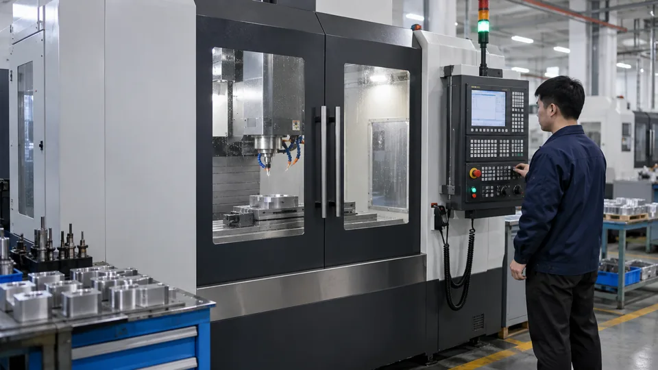
The broadest distinction is spindle orientation: vertical mills cut with a spindle approaching from above, while horizontal mills approach from the side. Construction also matters. A compact machining center, knee-type mill and large gantry machine carry different work envelopes and stiffness characteristics. Axis count describes controlled motion, not a guaranteed tolerance. Three-axis, four-axis and five-axis equipment can each make excellent parts when the part, fixture, tool and inspection plan fit the machine.
Start with the drawing: count the faces that need machining and identify which relationships must hold between them. A simple plate may suit a vertical three-axis setup. A housing with several side features may benefit from indexed rotary access. A broad panel might need a larger machine even if its geometry looks simple.
- Record overall size, weight and stock form.
- Mark required tool approach directions.
- Separate axis count from acceptance criteria.
Vastion’s machining service page provides a place to start a part-specific review. Haas’s mill operator manual illustrates vertical and horizontal layouts without implying a particular Vastion machine list.
Which label answers which question?
| Label | Describes | Does not prove |
|---|---|---|
| Vertical/horizontal | Spindle approach | Finished accuracy |
| Three/four/five axis | Available motion | One-setup capability for every part |
| Gantry/compact | Machine envelope and frame | Quoted tolerance alone |
2. When is a horizontal machining center useful?
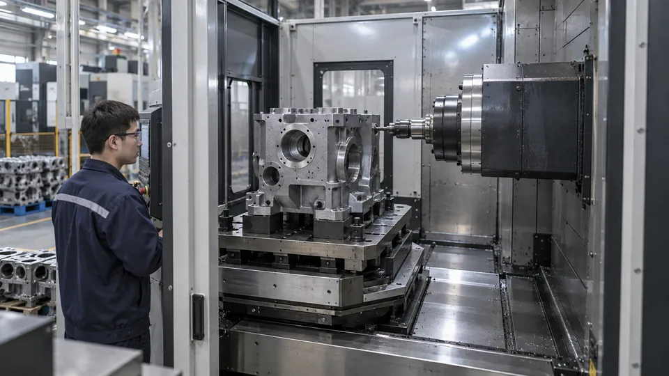
A horizontal spindle approaches the work from the side. This arrangement can make several faces of a prismatic part accessible when paired with an indexing table or pallet system. Chips may fall away from the cut under gravity, which can help in some cavity or heavy-removal jobs. Yet a horizontal center is not inherently better for every feature. Fixture design, spindle reach and the part’s datum scheme determine whether fewer setups are possible.
Think about orientation: a box-like housing with side ports might fit a horizontal plan, while a flat cover with broad top-face machining may be simpler vertically. Pallets can support repeat loading, but the buyer still needs a process that controls location and inspection across faces.
- Ask which faces can be reached per clamping.
- Check fixture and pallet clearance for your largest part.
- Confirm datum transfer across indexed orientations.
Request a setup sketch for a multi-face housing. If the main body could be made near-net-shape, compare the milling route with die casting using the same finishing and inspection requirements.
What makes a horizontal route worthwhile?
| Part trait | Potential benefit | Buyer check |
|---|---|---|
| Several side faces | Indexed access | Datum relationships |
| Deep side cavity | Chip evacuation | Tool reach |
| Repeat housing | Pallet workflow | Fixture ownership |
3. What separates knee-type mills from machining centers?
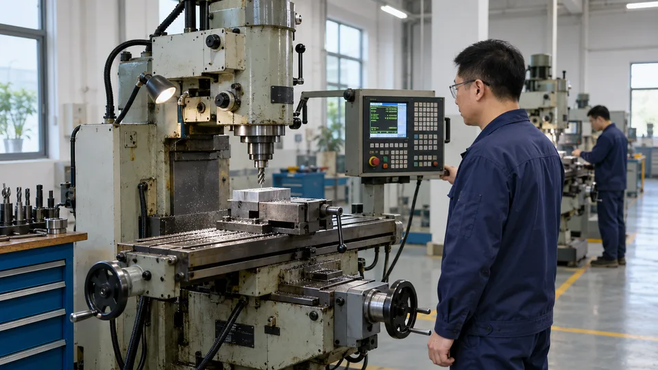
A knee-type mill raises or lowers its table on a knee beneath the spindle. Such machines can serve training, toolroom and smaller job-shop work, including CNC-retrofitted examples. A modern machining center commonly uses a more enclosed layout, automatic tool changing and production-oriented controls. These are broad categories; individual models differ. The buyer should not assume a knee machine is unsuitable or a machining center is automatically necessary. Part size, cutter load, setup time and required repeatability decide.
Ask about process stability: a small prototype with modest cuts may not need an elaborate production cell. A recurring order with many tool changes may benefit from an enclosed machine and repeatable tooling workflow. Both still need qualified setup and inspection.
- Match machine envelope to part and fixture.
- Count tool changes and repeat quantity.
- Request measured evidence for critical features.
Do not specify a machine category merely because it sounds more advanced. Specify the finished part and report package; let the supplier propose equipment and explain the tradeoff.
Which operating trait matters?
| Trait | Knee-type route | Machining-center route |
|---|---|---|
| One-off setup | Can be practical | Also possible |
| Automated tool change | Model dependent | Common feature |
| Repeat enclosure | Varies | Usually integrated |
4. What can a three-axis vertical mill reach?
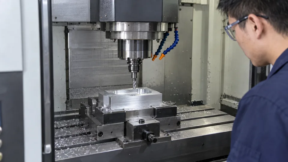
A three-axis mill controls motion along X, Y and Z. With a vertical spindle, it can cut accessible top faces, pockets, slots and outside profiles from one orientation. It may need another setup for a side port or the opposite face. A good two-setup plan can be more stable and economical than a poorly constrained rotary plan. The part’s datum surfaces determine how those setups relate to each other.
Accessibility sets the limit: a cutter cannot pass through solid material to reach an undercut. Deep narrow features may need a long tool that bends under load. Sharp internal corners inherit a radius from a round cutter unless a relief or secondary process is planned. These limits arise from geometry, not a lack of machine sophistication.
- Mark features visible from one tool direction.
- Identify relationships crossing setup boundaries.
- Allow realistic internal radii where function permits.
For shafts and round components, compare the primary geometry with CNC turning. Milling can add cross holes or flats after a turned datum is established.
Which feature needs a new approach?
| Feature | Three-axis access | Likely next step |
|---|---|---|
| Top pocket | Direct | Check depth and radius |
| Side hole | Not from same orientation | Re-clamp or rotary |
| Hidden undercut | Restricted | Special tool or redesign |
5. What does a fourth rotary axis change?
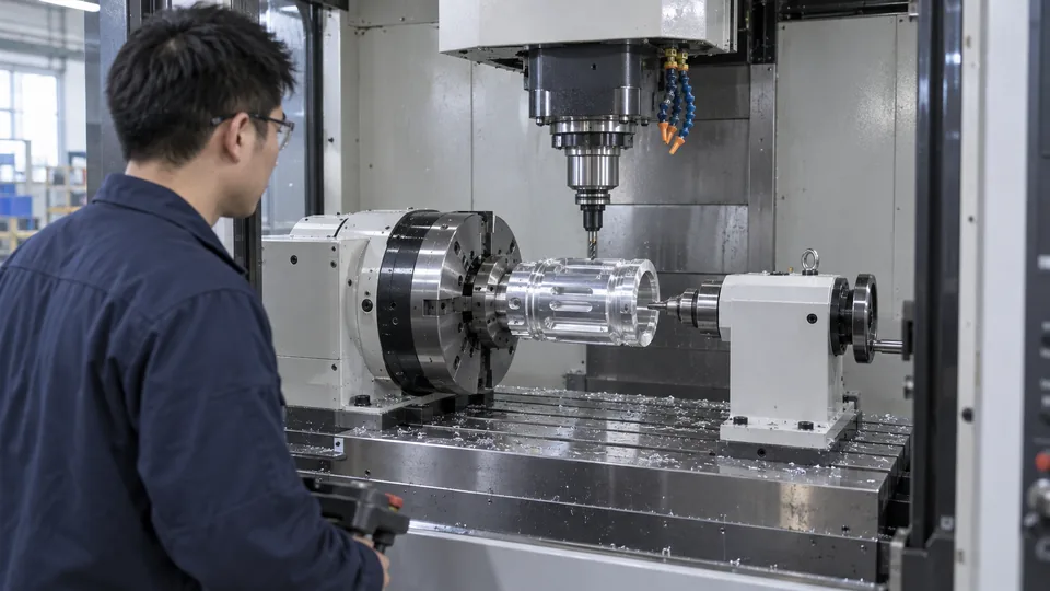
A fourth axis typically rotates the workpiece or a machine component around an additional axis. On a vertical mill, a rotary table can index a cylindrical or prismatic part so the spindle reaches more sides without manual re-clamping. That may improve positional relationships, but only if the fixture locates the part well and the rotary system is calibrated for the job. Rotary access also consumes table space and can limit part size.
One setup is not a magic phrase: some features remain hidden or require a separate orientation. A long tool may still be needed to clear the fixture. Buyers should ask which specific features are machined in the rotary setup and how their datums are measured.
- Ask whether the rotary axis indexes or cuts continuously.
- Check part size against fixture and table clearance.
- Confirm inspection of cross-face relationships.
For a repeat order, compare cycle time and fixture cost with a simpler re-clamp. The economical route depends on volume, not on axis count alone.
What does rotary access solve?
| Part need | Possible gain | Remaining question |
|---|---|---|
| Several radial holes | Indexed positions | Axis-to-datum alignment |
| Multiple side faces | Fewer manual setups | Fixture clearance |
| One-off sample | Access flexibility | Setup economics |
6. When does five-axis milling earn its extra setup work?
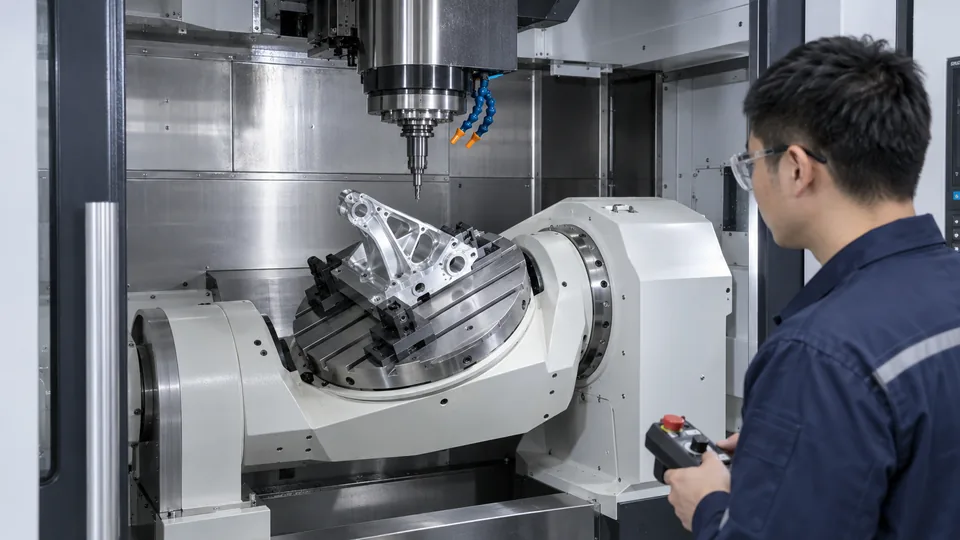
Five-axis milling adds another rotary degree of freedom, allowing the tool and workpiece to approach complex surfaces from more orientations. Indexed five-axis work positions the part between cuts; simultaneous motion changes orientation while cutting. The right method depends on geometry and finish. A sculpted impeller-like surface, angled hole pattern or multi-face bracket may benefit. A flat plate usually will not. Five-axis equipment also brings programming, collision, fixture and calibration demands.
Judge the whole process: fewer clampings can reduce certain datum-transfer risks, but a complicated setup can introduce different risks. Surface finish still depends on tool contact, step-over and rigidity. Inspection must verify the same functional requirements regardless of how many axes cut the part.
- Ask which features gain genuine access.
- Separate indexed from simultaneous requirements.
- Check tool, fixture and probe clearance.
Autodesk’s steep-and-shallow milling guidance illustrates why complex surfaces need considered tool paths; software strategy does not establish any supplier’s capability.
When is five-axis access justified?
| Feature | Potential benefit | Evidence needed |
|---|---|---|
| Angled faces | Improved tool approach | Setup and inspection plan |
| Freeform surface | Continuous orientation | Surface acceptance method |
| Simple flat plate | Little added value | Cost comparison |
7. What parts call for a gantry or bridge mill?
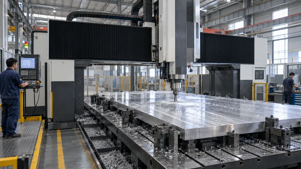
A gantry machine spans a broad work area with a bridge or overhead structure. It can suit large plates, panels, molds or frames that cannot fit a compact vertical center. Size brings distinct concerns: the part must be supported without sagging, temperature variation may matter across a long span, and inspection needs a method that covers the envelope. A large machine label does not remove fixture or datum work. Sometimes machining a smaller subassembly before joining it is more practical than milling one enormous blank.
Measure the complete envelope: add clamps, tool reach and travel limits to the part dimensions. A drawing width alone does not prove the work fits. Confirm lifting, loading and delivery constraints before ordering a large component.
- Include stock and fixture dimensions in the RFQ.
- Identify support points and free-state inspection.
- Plan handling and protective packing.
For large flat housings, compare a machined billet with sheet metal fabrication when the design allows it. Keep strength, flatness and finish requirements identical.
What changes as part size grows?
| Constraint | Why it matters | Buyer input |
|---|---|---|
| Machine travel | Access to all features | Full stock envelope |
| Part support | Sag and clamp distortion | Datum and free-state rules |
| Handling | Damage and safety | Weight and packing plan |
8. Where do compact drill-and-tap centers fit?
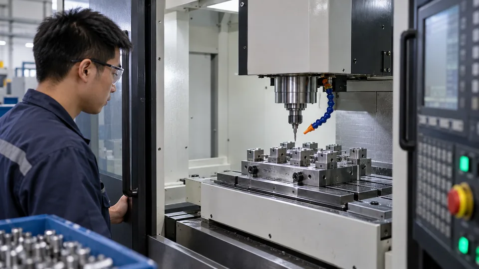
A compact drill-and-tap center typically emphasizes quick tool changes and efficient work on smaller parts with many holes or tapped features. Its work envelope and heavy-cut capacity may differ from a larger machining center. That does not make it a lower-quality option for a matching part. For small brackets or electronics hardware, a compact setup can be sensible. A deep heavy pocket in hard stock may call for another machine class.
Fit beats prestige: the buyer should compare the proposed tool, fixture, cycle and inspection plan with the print. Machine size does not tell you whether a tapped hole meets a thread gauge requirement. Nor does a fast tool changer remove the need for correct work zero and tool offsets.
- Check part and fixture dimensions against travel.
- List hole and thread acceptance methods.
- Ask whether heavy milling occurs elsewhere.
If the component includes a primary turned diameter plus drilled holes, a combined route with turning may reduce handling. Ask which operation creates the datum used for later holes.
What suits a compact center?
| Job trait | Fit question | Inspection need |
|---|---|---|
| Many small holes | Tool-change and fixture plan? | Position and diameter |
| Threaded bracket | Tap or thread-mill route? | Thread gauge |
| Deep heavy pocket | Enough rigidity and travel? | Wall size and finish |
9. Why do tool changing and production cells matter?
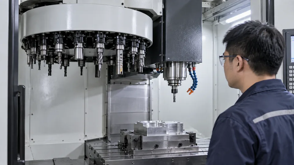
Two machines with similar axes can perform differently in a production plan. Tool magazine capacity, pallet change, probing, coolant delivery and chip handling affect how a job runs. A part with many distinct cutters may benefit from automatic changes and stable tool management. A recurring program may benefit from fixtures that load consistently. None of these features proves finished dimensions by itself; they help the process stay organized when paired with setup records and in-process checks.
Ask about the bottleneck: if coating approval takes longer than cutting, a faster tool changer may not shorten delivery. If quality checks wait until a batch ends, automation can produce more questionable parts before an error is found. Consider the full chain from stock to shipment.
- Ask which step controls delivery time.
- Clarify tool and fixture revision control.
- Define in-process checks for repeat lots.
For a custom program, start with the part’s acceptance package and material traceability. Machine features belong in the supplier’s process proposal, not as substitutes for evidence.
Which machine feature affects workflow?
| Feature | Potential benefit | Buyer check |
|---|---|---|
| Tool magazine | Fewer manual changes | Tool control |
| Pallet system | Repeat loading | Fixture location |
| Probing | Setup/measurement aid | Calibration and response |
10. Which CNC milling machine types fit your RFQ?

Send the complete part package and ask the supplier to propose machine type, setup count and inspection method together. The best route reaches critical features with stable tooling, controls datums across orientations and fits your quantity. A machine label alone cannot answer whether a surface will meet a specific tolerance after surface treatment or whether a cosmetic face will stay unmarked. Compare quotations against the same final requirements, not against advertised axis counts.
Use a simple decision rule: request an explanation whenever the suggested machine adds a complex fixture, unusually long tool or extra setup. Ask what alternative was rejected and why. For a first order, approve a sample or first article against the controlled revision before scaling the batch.
- Provide overall part and stock dimensions.
- Highlight critical faces, positions and finish.
- Request setup and measurement assumptions.
Use Vastion’s contact page to send the drawing. The industries page can provide application context, while your print remains the acceptance authority.
Frequently asked questions
Q1: Is a five-axis machine always more accurate?
No. Accuracy depends on the complete setup, machine condition, tooling, fixture, program and inspection.
Q2: Can a three-axis mill make parts with side holes?
Yes, often through a second setup. Rotary access may be another option if it benefits the job.
Q3: Is a horizontal mill always faster?
No. Its benefit depends on part orientation, fixture, chip flow, volume and other process stages.
Q4: Does a large gantry machine solve thin-part distortion?
No. Support, cutting sequence and free-state inspection still matter.
Q5: What machine detail should a buyer request first?
Ask how the proposed setup reaches and measures the drawing’s critical features.
